![]()
|
|
|
In
this model the cooling, oiling, sealing and ignition systems have been
developed and, as well as other secondary devices, to equipping it with
a stable operation independently of the time and work conditions.
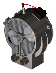
The cooling system is mixed, being made fundamentally by air forced on the outer surface of the cylinders (2a) of the rotor (2). The oil flow inside the stator (1) and inside the rotor, completes the refrigeration. The cylinders are shaped with wings externally. The flywheel (9) works as well like fan. When turning, their fans (9b) force to the air to circulate on the outer surface of the cylinders. The heat transference from the cylinders to the air is helped by two movements: the movement of the air that moves axially helped by the fan of the flywheel, and another one is the movement of the own cylinders, that when turning, affect this airflow perpendicularly. Of this form the cooling of the cylinders is very balanced in its entire surface. In operation, the interior of the rotor is crossed by a continuous lubricant flow in the form that will be explained in the oiling section. This lubricant at the same time that greases, cool the internal rotor and stator surfaces. IGNITION The ignition is made by a conventional system made up with the spark plug and a distributorless electronic ignition device (14) (DEI). The sensor will be installed on the flywheel, where the magnetic control pin (14b) is inserted. The position of the spark plug (6) allows an advance to the ignition of until 60 degrees. The engine also is able to operate with a system of continuous or synchronous injection of the fuel, being able to work in the "Miller" cycle. OILING
(fig.
26) The
oiling is made by forced oil flow, not being necessary to add it to the
fuel. The lubricant is deposited in the carter (1j). From the
carter the oil is aspired by a pump of gears (8) that is dragged
by the flywheel gear. The pump impels the lubricant at a first moment
towards the chamber of the oiler roller (11). This roller rotates
dragged by the central band of the seals (13) that also rotates
with the rotor. The function of the roller is lubricate and cool this
central band, against which it is applied, impregnating it a fine film
of lubricant when it turns. When the roller contacts with the central
band of seals, this one pushes it outwards, and the oil that is to
pressure in its chamber is expelled by the groove (1q) practiced
in the stator. When the roller lets be in contact with seals, which
takes place to the passage of the cylinders, its spring (11b)
applies against the stator, closing the window and the passage to it of
the oil. From
the oiler roller chamber the oil flow is led inside through the shaft
support arm (1l) toward the output shaft (2d), by whose interior
channel (2j) is geared toward the crankshafts (5),
lubricating them. From here go across inside the connecting rods (4)
and will be geared toward the heads of these lubricating them to be
finally expelled toward the interior of the pistons (3), to
refrigerate them. From here the lubricant is centrifuged by the rotor,
being expelled through the crankcase windows (2l) toward the
periphery of the rotor, lubricating the internal circular surface of the
stator. From here the lubricant will fall by gravity by the filler
outlet (1i), going to deposit itself again to the carter.
The toric seals (2k) along with the rotor outer seals (2i) provide a complete airtightness inside the rotor, preventing any oil escape outside. The combustion gas drained will be made of conventional form by means of a connection conduit from the oil-filling plug to the carburettor. SEALING
(fig 17, 18, 19
and 20) The
pistons are sealed with three conventional segment seals (3a) for
compression and oiling. The rotor semicircular seals are flexible and
are anchored in the cylinders heads. Here, this seal is branching
forming three semi-hoops seals segments in the form that is detailed in
the drawings. Its force of expansion maintains continuously and
uniformly applied them against the internal circular surface of the
stator providing complete sealing, as much to the cylinders heads as to
the intake and exhaust ports.
The
expansion forces in a semicircular seal are as follows (figure 20):
B.-
Force of recovery of the original radius (greater) on radio of the arc
(1). C.-
Circular force of expansion on the radius of seals (2). 1.-
The arc expands in radial direction, with regard to the rotor axis. 2.-
The 3 semi-hoops expand in radial direction, with regard to the cylinder
axis. CARBURETION
A
conventional external carburettor will be installed on the intake
conduit. |
|
|
| AC-800.- PHOTOS (Push on the image to see a large photo) |
AC-800.- DRAWINGS
| AC-800 PARTS | ||
|
Figure |
n. |
Part |
| 4 |
1.- |
Stator |
| 1, 2, 6, 7, 8 |
1a.- |
Intake port |
| 1, 2, 5, 6, 7, 8 |
1b.- |
Exhaust port |
| 1 |
1c.- |
Screws of the oiler roller |
| 1, 2, |
1d.- |
Lubricating oil filler body |
| 5, 10 |
1e.- |
Planetary support arms |
| 3 |
1f.- |
Oil drain plug |
| 7 |
1g.- |
Oil filler inlet |
| 1, 2 |
1h.- |
Engine bearer |
| 6, 7 |
1i.- |
Oil filler outlet |
| 4, 5 |
1j.- |
Carter |
| 2, 5 |
1l.- |
Shaft support arms |
| 4 |
1n.- |
Oil pump input |
| 1 |
1p.- |
Oiler roller cap |
| 6, 8 |
1q.- |
Oiler roller groove |
| 8 |
1r.- |
Dowel |
| 2, 8 |
1s.- |
Upper screws |
| 4, |
2.- |
Rotor |
| 12, 14, 17, 19 |
2a.- |
Cylinder barrel |
| 17, 19 |
2b.- |
Seals channel |
| 18 |
2c.- |
Seal bearer |
| 15, 16 |
2d.- |
Output shaft |
| 12 |
2g.- |
Cylinder head |
| 16 |
2h.- |
Dowel |
| 14 |
2i.- |
Rotor outer seals |
| 14 |
2j.- |
Oil central channel |
| 5, 16 |
2k.- |
Toric outer seals of the rotor |
| 4, 16 |
2l.- |
Crankcase window |
| 12 |
3.- |
Piston |
| 14 |
3a.- |
Piston seals |
| 14 |
3b.- |
Gudgeon pin |
| 14 |
4.- |
Connecting rod |
| 12, 14 |
5.- |
Crankshaft |
| 14 |
5a.- |
Balance weight crankshaft |
| 2 |
6.- |
Spark plug |
| 12, 15 |
7.- |
Satellite |
| 1, 5, 13 |
8.- |
Lubricating oil pump |
| 13 |
8a.- |
Gears |
| 13 |
8b.- |
Pump input channel |
| 13 |
8c.- |
Pump output channel |
| 3, 13 |
8d.- |
Pump gear |
| 1, 4 |
8f.- |
Oil input filter |
| 1, 3, 5 |
9.- |
Flywheel |
| 3, 5 |
9a.- |
Screw |
| 3 |
9b.- |
Fan |
| 1,2, 5 |
10.- |
Pulley |
| 5 |
10a.- |
Pulley screw |
| 10 |
11.- |
Oiler roller |
| 10 |
11a.- |
Roller pusher |
| 10 |
11b.- |
Roller spring |
| 10 |
11c.- |
Oil input |
| 8, 10 |
12.- |
Fix planetary |
| 10 |
12a.- |
Screws |
| 5, 12, 14, 16, 18, 19 |
13.- |
Seals |
| 17, 19 |
13a.- |
Pusher spring |
| 3, 9 |
14 |
Distributorless electronic ignition device |
| 3, 9 |
14a |
Flywheel sensor |
| 3 |
14b |
Control pin |
| 3 |
14c |
Spark plug wire |
|
|
||
![]()
|
|
|
|
|
|
|
|
|
|
|
|
|
|
|
Antonio Sánchez 1997-2007. Málaga (Spain) |