![]()
 |
|
This engine is assembled with a stator that houses a cylindrical rotor.
This rotor contains two transverse cylinders. Within each cylinder is
displaced a piston that is connected to its crankshaft through a
connecting rod. Each crankshaft is geared through a satellite with a
fixed planetary in the stator. In operation, all its mobile parts rotate
in a way continuous in a unique direction. Distributed passive ports
perform intake and exhaust operation. The operation principle is based
on the alternative acceleration and deceleration of the pistons in
relation with the rotor. The 7 mobile parts are all rotary. Pistons and
connecting rods describe a path "quasicircular". This engine
is circularly symmetrical with a central shaft. The eccentric forces
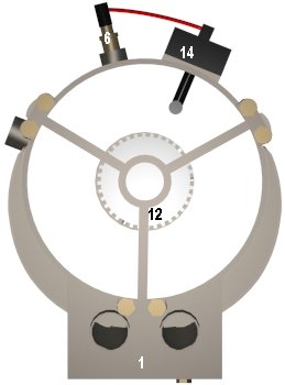
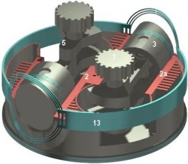
within the engine are balanced by mutual cancellation. The Hybrid Engine is composed by thirteen main parts: the stator (1), the spark plug (6), and a rotor (2) that houses two pistons (3), two crankshafts (5) two connecting rods (4), two satellites (7) and two seals (13). Each satellite rotates solidary with its crankshaft and is permanent geared with the planetary (12). This planetary is stationary. When the rotor rotates, the parts that it houses ( pistons, connecting rods and crankshafts ) rotates with it, and simultaneously the satellites are forced by the planetary to rotates on its own shaft in the same direction of the rotor, but with double speed that this because the diameter of the planetary is double that the diameter of the satellites. A complete rotation of each crankshaft is converted by its connecting rod in two reciprocating movements of the pistons, resulting that, when the rotor rotates, the pistons are slid inside the cylinders being advanced and being delayed in relation to the rotor. This operation produces a space of variable volume inside the cylinders (2a). The rotor as well as the crankshafts rotates in a unique direction, that show in the operation section, equal to the movement of the needles of the clock. This is the norm followed to express the angle measurements. |
Stator |
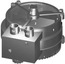
STATOR The stator (figures 6, 7, 8 and 10) is a hollow cylinder that houses the rotor. The planetary is located in its rear part. The intake distribution port (1a), the exhaust distribution port (1b), and the spark plug, are located in its circular surface. The Intake and exhaust ports occupy contiguous positions on the stator, being separated 10 degrees. Each port encompasses 95 degrees. Between these ports is located the spark plug, separate 93 degrees of the beginning of the exhaust and 67 degrees of the end of the intake. The two distribution ports lead and regulate the intake and exhaust gases toward or from the cylinders. |
|
SPARK PLUG/INJECTOR It is employed an only spark plug, that has the function of inflaming the mixture that is dragged inside the cylinders.
|
| ROTOR
The
rotor (figure 14,
15
and 16)
is a cylindrical part that contains two hollow cylinders located
transversely. These cylinders are parallel and opposed between if. Each
cylinder is opened toward the stator in its front extreme. The rear side
houses the crankshaft. The rotor rotates on its own shaft (2d),
being slid on the stator. The rotor operates at the same time as
inertial flywheel, accumulating part of the energy in the power phases. Each
cylinder contains a piston with its connecting rod and crankshaft (figure
14). A
circular seal (13) is housed about the front extreme of each
cylinder, in the outer rotor surface (figures 17,
18,
19
and 20).
Each seal is anchored about the front extreme of each cylinder, creating
an elastic circular band around the rotor. This seal is branching about
the cylinders heads forming three segments. Each seal is maintained
continually applied against the stator. This seal have the mission of
assuring the integral airtightness inside the cylinders and between the
cylinders and the ports Each piston is connected to the crankshaft through a connecting rod articulated in both extreme. The connecting rod converts the revolving movement of the crankshaft into reciprocating movement of the piston. Each piston head have oblique profile, in order to creating a "spherical" butt-end chamber that improves the combustion process. This configuration furthermore increases significantly the contact surface of the piston with the combustion chamber, increasing the power efficiency. |
|
OILING The oiling device is explained in the AC-800 Section. |
|
|
|
|
|
|
|
|
|
|
|
|
|
|
![]()
![]()
Antonio Sánchez 1997-2007. Málaga (Spain)