RF Directional Couplers
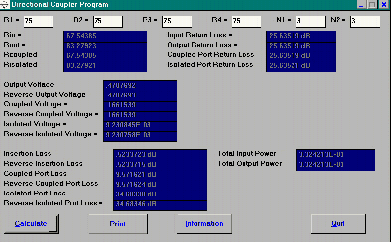
This software designs RF directional couplers. The program is completely described in the Feb. 1997 issue of RF Design Magazine, pp 30-44. It tells the number of turns needed for a binocular core directional coupler to achieve a desired coupled port loss. Theoretical values of return loss and insertion loss are also provided by the program. Programs for DOS and Windows are available with source code.The input screen is shown below for the design of a 10 dB directional coupler.

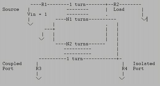
This program calculated parameters for transformer based directional couplers where R1 is the source impedance, R2 is the load impedance,R3 is the impedance seen by the coupled port, and R4 is the impedance seen by the isolated port. In the reverse mode, R1 is the load impedance, R2 is the source impedance, R3 is the impedance seen by the isolated port, and R4 is the impedance seen by the coupled port. Reference the figure below for the forward mode.

send email to Mike Ellis