3.10 The Accident according to the Commission - Damages to the Fore Ship and the Ramp - the Hole in the Superstructure forward Side behind the Visor
If the visor, previously attached to the superstructure at five (three locks and two hinges) or seven (including the lifting pistons/the actuators) strong points, actually was lose at 01.08-01.12 hrs according to the Commission, it should have rested on the ship as follows:
the two visor hinge arms port and starboard (they are intact and straight but ripped of at the hinges) would have rested on the upper superstructure #4 weather deck and the bottom of the visor, it is not particularly damaged, would have rested against the #2 forepeak deck on top of the hull.
You would then have expected to find scrape marks and green deck paint on the underside of the visor hinge arms but no such marks can be seen. You would also expect the #2 forepeak deck to be damaged but it is intact (based on video films).
The visor lifting hydraulics pistons are at this time still hanging inside the superstructure through openings in deck #4. Now the lugs below the visor arms or the lifting pistons cut forward through the deck beam at frame 159 according to the Commission.
After having cut forward through the #4 weather deck plating and the deck beam, the lose visor should then have ended up in a position shown in figure 3.10.0 below. The aft wall of the visor ramp housing is alleged to be pushing against the ramp top and there are some bent stiffeners inside the housing port side indicating a contact with the ramp. The Commission suggests that these damages were caused, when the visor pushed the ramp forward, but they could be old contact damages. You would have expect more scrape marks inside the visor housing, if the visor had actually pushed forward against the ramp.
The lugs of the lifting hydraulics on the hinge arms have cut or are in the process of cutting through the deck beam at frame #159. There are no active attachments between visor and ship superstructure - the visor is lose. The visor is allegedly tipping forward by its own weight against the ramp. If vertical, upward and horizontal, aftward (the ship moves forward at 15 knots), wave loads in excess of the visor weight now acted on the visor, these wave forces try to lift the visor (filled with water) up, above the ramp, and aftward, and when the wave force ceases, the visor may crash back down on the open #4 weather deck and the #2 fore peak deck.
|
However, there is no evidence that the #2
forepeak deck or the #4 weather deck or the
undersides of the hinge arms are damaged due to
such movements. Actually - model
tests show that the waves cannot lift
the visor! It is too heavy and the wave loads are
too small!! And there is very hazy evidence that
the visor cut through #4 deck - see below! The actuator lifting lugs must (or has already) at the same time (iv) 'cut' forward through the
deck plate and then deck beam at frame #159 on both
sides of the ramp. |
|
In the Part Report (16) the Commission states April 1995 that
"The (superstructure #4 upper) deck was torn open from the visor operating actuator openings and forward (figure 11.4 (see below) ). The openings continued for some length down the front bulkhead (figure 11.5 (see below)). The deck damage was extensive, while the openings in the bulkhead had rather clean-cut edges".
That is all. Not a word about the frame #159 deck beam. The Commission was apparently not aware of the deck beam in April 1995!
The Deck Beam at frame #159
The Independent Fact Group has shown that one lifting lug cannot cut the deck beam http://factgroup.tripod.com. The deck beam at frame #159 is thus another mystery.
The weather deck plate of the superstructure is 8 mm and the four 'cutting edges' are four 20 mm thick lifting lugs of steel plate (about 400 mm high) - one pair on each side of the ramp. The 'cutting edges' in each pair are about 100 mm apart, i.e. they should cut two 100 mm wide openings in the deck. When 'the pairs of cutting edges' arrive at the deck beam at frame #159, after having cut 120 mm of deck plate, they shall first cut a 100 mm wide opening downward (!) through the beam vertical web plate, 8 mm thick and 400 mm deep (!), and then through the beam face flat - a 22 mm thick and 160 mm wide steel plate (!), which is 400 mm below the deck. How the visor arm lugs can cut 400 mm downward is not clear - the underside of visor arms rests on the weather deck. Or was the beam web and face flat torn/cut by the hydraulic cylinder? There are no pictures whatsoever of the cut off deck beam port and starboard in the Final Report (5) or in the available video films! It is very strange that the divers did not examine and photograph the deck beam in December 1994.
|
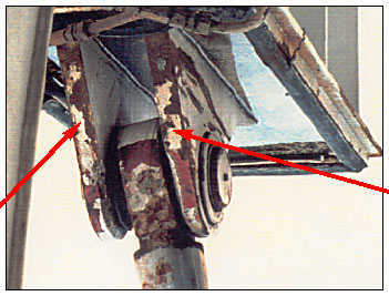
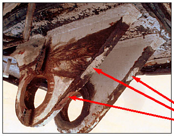
It is interesting to note that the 'cutting edges' (the lugs) and the cut material consist of the same material - normal grade A ship steel. According the Fact Group you need a force in the forward direction >185 ton to 'cut' through the 22 mm face flat (400 mm below the weather deck) during the whole cutting time. Where did this force come from? Did it exist? All the wave loads on the visor acted upward and in the aft direction! The port visor actuator lifting lugs below the visor arm and its lifting piston are shown in figure 13.10.1 right. The two lugs, where white paint is still visible, are alleged to have cut through steel! And how could the cutting edge on the visor arm lugs cut structure 400 mm below the deck from aft to forward? The cutting edges of the lugs seem to have been in the air flat in line with the open weather deck no. 4 above the face ! The pistons of the lifting hydraulics were still attached to the lugs. Did the round hydraulic cylinders or the round piston rods cut throught the beam? The actuator piston is still painted white! |
actuator after the accident and after having cut through deck plates and deck beams. The paint on the lugs' forward and inside edges remains! |
The Commission has never investigated the matter and the Final Report (5) only concludes that the beam was cut port and starboard by the lugs (there is evidently no photo evidence) - but how? What kind of damages could the lugs do? It is in fact impossible that the lugs can 'cut' the beam.
Unclear Evidence of any Damages
|
Right is figure 11.4 from (16) with a very unclear picture of the allegedly 'extensive deck damages' from film taken on 2 October 1994 1.4. It is an alleged close-up of the port side #4 open deck on 65,2 meters depth - the time is 13.52.56 hrs. The picture is upside down in the Part report (16). The Commission states that the port side deck plate damages on the top of the superstructure, deck 4, are caused (cut) by the lifting lugs - 'the cutting edges', (see figure 13.10.1 above). The writer cannot judge the picture 13.10.2. Where are the extensive damages? Where is the 100 mm wide opening cut by the lugs, so that we can see the plate edges? Where is the deck beam? The deck was apparently painted green but we cannot see any green structure on the picture. |
Figure 3.10.2 - Fig.11.4 of the Part Report (16) - 'Damages on the #4 deck caused by the lugs of the visor hydraulic cylinder' according to the Commission. |
The front bulkhead was on the other hand painted white.
Why weren't better pictures made by the divers inspecting the damages in December 1994? Is it actually deck #4 forward we are looking at? Or is the picture of something else? Just shown to confuse the public?
|
Right is figure 11.5 from (16) shown with another very unclear close-up of allegedly 'the openings in the bulkhead with rather clean-cut edges' and which 'continued for some length down the front bulkhead'. It is a close-up of the port side bulkhead at 64.5 meters depth taken at 13.50.59 hrs. The picture is turned 180° compared with the picture in figure 3.10.1 above. The Commission states that the damages on the port side front bulkhead of the superstructure were caused by the hydraulic cylinder, i.e. not by the lugs. The writer cannot judge the picture, which should be a continuation forward of the picture in figure 3.10.2. Where is the front bulkhead? Where are the damages with the 'clean-cut edges' - in the lower part of the picture? |
Figure 3.10.3 - Fig.11.5 of the Part Report (16) - 'Damages on the front bulkhead caused by the visor hydraulic cylinder' |
How can a round hydraulic cylinder (see figure 13.10.1), or its piston rod, cut through a plate? And why were there no scrape marks on the white painted port hydraulic cylinder indicating that it should have cut through steel (the paint on the cylinder is virtually intact!). And how much did the damage extend down the bulkhead? Why wasn't a better photo made by the divers in December 1994?
The conclusion is that the above picture does not show what the Commission suggests! It is only published to confuse the public!
In the Final Report (5) chapter 8.5.2 (page 121) the Commission, states that the damages on the green weather #4 deck and the white front bulkhead of the superstructure were as follows:-
"The #4 deck was torn open from the visor operating actuator openings and forward. The openings continued for some length down the front bulkhead. The deck damage was extensive with uneven fracture whereas the opening in the front bulkhead on the port side had rather clean-cut contours (figure 8.2 (see below))."
That is all. The green #4 deck had 'uneven fracture', while the white port side bulkhead had 'clean-cut contours'. But how was the #4 deck beam port and starboard cut? And the damages on the starboard side bulkhead? Why weren't they filmed? And what does 'some length down the front bulkhead' mean?
The above two figures are the only evidence shown by the Commission that the visor had fallen off the ship and caused the rest of the accident. Not very convincing, to say the least!
|
To see the area of the superstructure we are studying figure 8.1 from (5) right refers. Only the allegedly damaged weather #4 deck and the front bulkhead of the superstructure are shown - the deck beam, frame #159, is not shown. The starboard bulkhead is only torn at the upper part. Figure 8.1 above says that there is an 'impact hole' in the starboard bulkhead just above the side lock. That particular damage is not further investigated in the Final Report (5) and as will be shown below, the real damage is a big opening about 60 centimetres wide and two meters high (long) - which the Commission has carefully avoided to film, analyse and report. It also indicated 'damages' in the starboard bulkhead below the side lock, but these too are not further described in the Final Report (5). |
Figure 3.10.4 - Fig. 8.1 of the Final Report (5) - 'Summary of damages in the bow area' |
The damaged hole on the starboard side is much wider than, e.g. the starboard hydraulic cylinder. We know that the paint work of the starboard hydraulic cylinder is undamaged. The cylinder could therefore not have caused the damage to the bulkhead. What caused it?
The situation is thus that the Commission has reported and shown very unclear pictures taken 2 October 1994 of alleged damages on the green weather deck #4 of the superstructure and the white top of the bulkhead just below the superstructure top #4 deck, which it suggests to have been caused by the visor lifting lugs, see figure 13.10.1, and hydraulic cylinders, when the visor fell off. Furthermore, there are damages/impact hole further down on the starboard bulkhead, which are not described at all by the Commission.
|
Another sketch of the same damages filmed on 9 October 1994 1.14 is the appendix to the fax of Karppinen on 10 October 1994 (act I16) right. Note that there are no damages on the starboard bulkhead above or below the side lock (A). Only at the top is a damage (B) - 'torn out plate'. But there is a 2-3 meters high and 0.5-0.6 meters big hole there - see below! At 23.16 hrs a mysterious 'orange box' was filmed in the vicinity of the port locking pin (A), which is not marked on the drawing 4.1. |
Figure 3.10.5 - Appendix to fax 10 October 1994 - 'Summary of damages at the bow' (act I16) |
The Visor was attached to the Wreck on the Sea Floor
Another interesting note is F (on starboard side) 'Hinge pin fallen out from the eye pad. Visor arm broken'. Evidently you cannot see any visor arm on the picture and the visor had not yet been found, so why would anybody write on a fax on 9 October that the visor arm was broken? If the hinge pin had fallen out, the visor arm could very well have been undamaged. Or could you see the visor (!) and the damaged visor arm on the original film? There are many indications to this effect, e.g. that there are no scrape marks whatsoever on the starboard hydraulic cylinder and very few marks on the lugs. The starboard cylinder should therefore have been pulled out, when the ship had >120° list on the sea floor! The visor was thus still attached to the wreck then!
|
The only 'evidence' in the Final report (5) that the #4 weather deck (painted green) and front bulkhead (painted white) are damaged is shown right - Figure 8.2 from (5). This picture - which according the Commission shows a close-up of the port green #4 deck and white bulkhead in front of the opening for the visor operating actuator in the superstructure - is only figure 11.4 from the Part report (16) - see figure 3.10.2 above - turned upside down to a correct position as seen by the ROV with arrows indicating Bow and Port! Where are the 'uneven fracture' in the green painted #4 deck and 'clean-cut contour' in the white painted bulkhead? And why are the damages on starboard side not shown? |
Figure 3.10.6 - Fig.8.2 of the Final Report (5) - 'Damaged deck and front bulkhead in front of the opening for the visor operating actuator on the port side' |
The picture is taken by an ROV on 2 October 1994, and the same area - and the starboard side - should have been filmed on 9 October 1.14. In December 1994 1.16 the same areas were again filmed by divers.
But why were not better photos taken by the divers in December 1994 of (a) the superstructure #4 deck, (b) the superstructure bulkhead and (c) the deck beam on both sides - port and starboard - to record the alleged damages and particularly the edges clearer?
If e.g. the deck beam was cut off port and starboard it would have been easy to film it - but today there exist no video films or photos of any cut off deck beam. Many persons do not believe that the beam is cut. This writer believes that the visor was still attached to the wreck, when the film of 2nd October was taken, and that the visor was later removed under water before the second film was taken on 9th October - to verify the removal.
Only Port Side filmed
It is only damages on the port bow side (the upper side of the wreck), which are allegedly shown on above (and other) pictures taken and copied from films taken on 2 October 1994. The pictures are very bad and difficult to interpret and do not prove anything, including the loss of the visor at the surface of the sea.
No pictures of damages on the starboard side from that film have been published by the Commission, which is an indication that the visor might still have been partly attached to hinges and lifting hydraulics there on 2 October 1994! This conclusion is supported by the fact that there are no scrape marks on the starboard cylinder suggesting that it should have been pulled out through ripped open steel before the 'accident' started.
The visor could very well have been only partly detached, when the list was >100 degrees and some port side attachments of the visor were broken and visible, so that some port side parts could be filmed. But it is quite probable that the visor was still attached on the starboard side and that, e.g. the starboard hinge pin fell out, when somebody tried to remove the visor under water after the accident.
We must not forget that Dr. Nuorteva on four sonar pictures taken on 30 September 1994 had observed an object at the bow, which looked like the visor 1.4. The films allegedly taken 2 and 9 October 1994 at the bow also seems to be edited only to show selected parts of the port side of the superstructure. The excuse - that the films showed human bodies at the wreck - cannot be accepted. There were no bodies outside the wreck at the bow! And later no better pictures of the alleged damages of the superstructure were later done at, e.g. the diving in December 1994.
The Commission lied
In view of the fact that the Commission 1994-1997 lied about every essential fact of the accident and produced a totally false sequence and plot of events 1.9, it is very likely that above pictures do not show the alleged damages in the forward port side superstructure caused by the visor. The pictures are simply extracts from the 2 October video film of some other, damaged part of the hull. The figure 8.2 of the Final report (5) and the figures 11.4 and 11.5 of the Part report (16) are simply clever disinformation to mislead the public. The Commission knew that it had succeeded to fool the public with the pictures in the Part report (16) in April 1995. Therefore it just repeated the stunt in the Final report (5) in December 1997. The simple conclusion is that there is no evidence that the starboard visor lugs and cylinder ever cut through the superstructure.
The big Hole in the Starboard Front Bulkhead
At a private dive expedtion 2.24
in August 2000 parts of the starboard front
bulkhead of the superstructure was filmed - see
picture (right). Unfortunately the starboard #4
weather deck, the deck beam and the upper part of
the bulkhead were not filmed. The reason was that
the divers found - and then concentrated on - and
filmed a very big hole - 2 meters long and 60 cms
wide in the starboard front bulkhead just
above the side lock in an area, which the
Commission had reported as undamaged (or with
an impact hole without further explanations). The
edges of the opening are partly bent outward,
partly cut off and most of the original material
has disappeared. It is self-evident that the opening cannot
have been caused by the starboard hydraulic
cylinder ripping through the bulkhead. It is
evident the hole is caused by explosives! The opening is wider than the cylinder,
plate material is missing and the bulkhead
above the opening does not appear to be damaged,
and there are no scrape marks on the cylinder
itself! Two test pieces were cut out from the edges and
has since been analysed by several laboratories.
Preliminary results show that the material has been
modified due to an explosion. Did the hole (and
explosion) occur when the visor was detached under
water 4.1?
The opening cannot have been caused by the
starboard hydraulic cylinder pulling out of the
ship 2.24.
The damage has never been reported by the
Commission or described in the Final Report
(5).
|
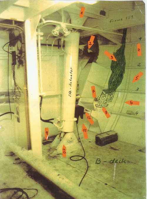
The picture has been shown in Germany (Focus TV, Spiegel TV, Der Spiegel 5/01 page 135) and in the Czech Republic (Nova TV) in January 2001.(The picture is of the front of the white painted bulkhead (starboard side) against which the visor rests in the closed position - there is a 5-10 cms gap between visor/bulkhead except at the rubbers and other contact points. The surface is now covered by dark mud.) The reader should note that above damage is not indicated at all on the damage report of Mr Karppinen faxed to Stenström on 10 October 1994 in figure 3.10.4 above. In figure 3.10.7b right we can see the damage in the starboard forward bulkhead sketched in on a photo of the area (before damage occurred). Arrow 1 shows the actuator lug that is alleged to have cut through the strong deck beam at fr. #159. Arrow 3 shows the plate that has been ripped open and that has disappeared. Arrow 4 shows the first horizontal stiffener of three that also have been cut ... and disappeared. Arrow 6 indicates the location of the rubber seal channel on the outside. When and how did this damage in the starboard front bulkhead occur? While removing the visor under water after the accident between 2 and 9 October 1994? The visor was then resting against the outside of the bulkhead and one or more explosive devices applied between the horizontal stiffeners blowed it away causing the hole in the bulkhead and also some indents in the aft bulkhead of the visor itself! |
|
It is very easy to verify - just check again the original MASTER film taken on 2nd October 1994 (and not the edited copy made available) and look at the visor.
The Commission alleges that after all visor attachments were broken, actuator lugs, cylinders or piston rods cut through and/or ripped open a lot of steel structure in the superstructure, when AB Linde was waiting at the reception and 3/E Treu was fiddling around in the ECR. All this destruction should have caused large noises sometimes between 01.05-01.10 hrs. The Commission cannot comment upon this - they just refer to 10 minutes of metallic noise between 01.02 and 01.12 hrs noted by 'several anonymous witnesses' when the ship made 15 knots forward speed and nothing unusual had happened (except the noise).
That the survivors experienced the sudden list >30 degrees starboard already at 01.02-01.05 hrs and then were escaping must be censored by the Commission. If the sudden list took place at 01.02 hrs, then the visor got lose at say 00.52 hrs, when Linde was allegedly checking the ramp on the #2 car deck - and heard nothing.
Of course we know today that the whole story of the visor is nonsense: with water inside the superstructure the 'Estonia' should have capsized and floated upside down - and it never happened.
No Scrape Marks
|
Most of the white paint remains on the visor hinge arm lugs particularly on their ports sides - see e.g. figure 10.2 in the part report (16) of the starboard lugs and figure 13.10.8 right - all paint remains. Figure 8.9 (also 8.4) in the Final Report (5) shows the starboard side of the port side lugs, and there are some score marks, but all paint should have been removed after alleged cutting the deck plate, the beam web plate and face flat, etc. and on the other side of the lug all the paint remains. The paint on the starboard lugs forward edge (figure 10.3 in (16)) and on the port lugs forward edge (figure 8.9 in (5)) remains - it is evidently not possible, if these 'cutting edges' had cut steel. There should also be scrape marks on the undersides of the hinge arms themselves and green deck paint from the #4 weather deck of the superstructure. No such marks can be seen. And evidently there should be more scrape marks inside the visor housing if it had been in touch with the ramp. And finally, there should be scrape marks on the starboard cylinder, if it had cut through the superstructure plate and beams. But its paint is undamaged. |
|
The visor itself is the best evidence that the visor did not fall off as alleged by the Commission. Actually all information given by the Commission to the effect that the visor fell off at sea is not supported by any evidence at all.
The Ramp opens
No known survivor heard anything from the bow between 01.02 and 01.12 hrs, as in reality the vessel had already listed at 01.02-01.05 hrs, and all witnesses were in the process of saving themselves. But the Commission presents another story - fairy tale!
According to the Commission the visor housing now - say at 01.12 hrs - pushed against the ramp top and detached the ramp from its hooks and locks. The evidence should be three, four bent stays inside the visor housing (see e.g. figure 8.7 in (5)) but no other score marks. It is quite amazing that the whole inside of the visor housing has no score marks or that the aft edge of the housing is not damaged at all. Thus two hooks and four looks of the ramp 3.4 were allegedly torn apart by strange forces on the visor in the forward direction of > 30 tons, while the visor housing was almost intact.
According the Commission this occurred at about 01.13 hrs.
What actually happens, if a lose Visor tries to push open a locked Ramp?
3-D FEM (three dimensional finite element) calculations done by the writer show, e.g. that a 10 tons symmetrical, forward force on top of the ramp caused by the visor weight 55 tons,112 results in a 7.7 tons pulling force in each locking hook one meter below the top of the ramp113 - the ramp rotates around the hooks and pulls the hooks forward, while it pushes against the lower side locks - the upper locks with 2.2 tons, the lower locks with very little force. If the forward 10 tons push force is asymmetrically applied at the port ramp edge, the pulling force in the port hook increases to 14.0 tons and is reduced in the starboard hook to 2.1 tons. The ramp pushes against the port upper side lock with 5 tons, etc.
A load due to the weight of the visor tipping forward on the ramp, could not pull open the ramp.
A 30 tons asymmetrical forward force on port ramp top in contact with the inside of the visor housing should in principle pull apart the top port ramp hook (and damage the visor housing). But from where did that forward acting force originate?
All wave loads were always pushing the visor aftward (or upward). The Commission does not provide an explanation how the loads were pulling forward and downward.
A forged upper ramp hook has an area in its arm 18.75 cm² - with break stress 4 000 kgs/cm² the hook arm can resist 75 tons: evidently the shaped forged hook tip breaks earlier - say at 25-40 tons, unless the pin, around which the hook grips, breaks (shears off) even earlier. It would have been easy for the Commission to prove that the ramp had been pulled open - it is only to show (photos of) two broken ramp hooks or pins. But the Final Report does not show any damaged ramp hooks or locks at all! And by observing the underwater films it seems that the hooks are undamaged. According to the Germans the ramp could not be locked! It was twisted and the locks and hooks didn't fit any longer.
To secure the ramp a rope was simply slung around the top and secured on the weather deck. Thus the ramp was secure!
Then the visor was closed - but due to the rope the visor could not be locked either. So the visor was secured only by the lifting hydraulics - and it worked! The heavy visor hardly moved due to ship motions, and the ramp was secure. Only a little water may have leaked in.
It is impossible that the ramp was pulled open by a forward force of say 30 tons on the ramp port top, when the visor was lose, in spite of the small observed damages inside the housing, which could have been caused earlier (or later).
The Writer does not believe the Ramp was open at all!
There are no witnesses who have seen an open ramp 1.4.
The writer wrote an article about the above in the Royal Institute of Naval Architects' magazine the Naval Architect in 1998. It resulted in a reply by Karppinen and Huss to the effect that
"the mating boxes of the ramp side locks were ripped open".
But that was not true. The mating boxes area actually visible on the video films taken 1994 and made available to the public 1998. They are not damaged! Beacuse the ramp was never locked and thus the locks could not have been ripped open.
Observations by Mr Johan Ridderstolpe
Johan Ridderstolpe of the Independent Fact Group has studied all the video films and has informed the following:
"... the mating pockets of the side locks of the ramp are virtually intact and not ripped open as stated by the Commission.116... it is quite clear that the ramp was not properly locked prior to the loss of the visor. The ramp lock pins were extended but not into the mating boxes, probably to activate the indication that the ramp was locked ... (the pins extended into air above the boxes)
...The Final report says: "The bow loading ramp was found slightly open, with a gap of about one metre at the top". I have checked the films and note that on the early films the opening is only 10-30 cms.
On later films the ramp is more open 40-60 cms and on the latest film 1 meter. ...
... that attempts have been made to open the ramp at the bottom of the sea is quite clear".
No such attempts were reported at the dive examination in December 1994 1.16. It is thus possible that the ramp was not locked at departure from Tallinn before the accident but only put in a partly closed position with help of ropes, etc. as the Germans also suggest 3.17. Furthermore by Ridderstolpe:
"The lower part of the ramp is totally closed. ... The ramp is bent slightly forward ...... the mating pockets of the side locks of the ramp are virtually intact and not ripped open as stated by the Commission ... there are some fractures in the mating pockets connections to the ramp itself , but they are not the result of any ripping open the ramp. The locking pins are too long to slide out of the pockets ...
If the ramp was actually properly locked, the mating boxes should have been completely ripped open - and they are not ripped open.116"
Guard Rails removed
Ridderstolpe has produced other indications that the ramp was never open:
"The guard rails welded on the ramp sides117 have been removed under water ... on the early films you can see the guard rails ... on all later films the guard rails have been cut off ... it is obvious that the guard rails have been cut off below water, as they prove that the ramp was never open ... the ramp guard rails would have been damaged by the locking pins of the ramp ... these pins are extended from the frame and should have been fully inside the mating boxes ... the length of the locking pins is such that they would grip into the guard rails, which are flush with the frame ... furthermore - the guard rails had folding parts at the top of the ramp ... if the ramp had been opened and then closed, when the ship sank with a big list, the folding part would have got stuck between the ramp and its frame - the ramp would never have closed again ... etc., etc. ".
What Ridderstolpe hasn't noticed is that the guard rails can be seen on the seabed on an ROV video film already on 2 October 1994, i.e. they must have been removed before then. But how and by whom? No divers had officially visited the wreck at that time - it didn't take place until 2-4 December 1994 1.16.
This writer therefore concludes that divers visited the ship already on 30 September and 1 October. These divers were probably Swedish because the Swedish navy (HMS Furusund) had immediately anchored up at the wreck. What they did - except having a look around - is described in other chapters of this book. They probably tried to open the ramp and to remove the visor! And they succeeded.
They blow off the visor using explosives under water! And then the starboard visor lifting cylinder slipped out of the deck hole without any scraping, etc. Then they pulled apart the hinges and the visor fell to the bottom below the wreck! There were no scrape marks on visor lugs and arms.
A final remark is that not only the side guardrails would have prevented the ramp closing: also the starboard ramp lifting hydraulic cylinder would have stuck out and prevented the closing, if the ramp were ever open.
The Inside of the Ramp not examined
The Commission in the Final Report (5) states that the inside of the ramp and the car deck were never inspected by them (or anybody), even if it is clear that a survey of the car deck was requested by Smit Tak and carried out. Ridderstolpe has seen several videos taken 2-4 December 1994 1.16 where divers and an ROV (sic) operate inside the car deck. The ROV should have entered through a 'hole' in the starboard side! - it could not get through at the ramp itself. The 'hole' was probably the open starboard pilot door 1.4. It seems clear that the car deck was in fact inspected and filmed at the request of the Commission (or Franson), but that most films were edited later because they showed that (i) the ramp locks were undamaged and (ii) that divers removed the guard rails on the ramp (probably in September/October 1994) in an attempt to open the ramp.
Ridderstolpe thus supports the suggestion that the ramp was never open during the accident - not before nor after the list. Ridderstolpe concludes that the ramp was not even locked, while the Commission states that the ramp was locked, before it was detached by the visor 1.15.5. AB seaman Linde has stated that the ramp was closed and that no water leaked in.
The Germans suggest that the ramp was held in place by mooring ropes around the top of the ramp at departure Tallinn; the ropes were secured on the upper, no. 4 weather deck.
Ridderstolpe has stated that divers were inside the car deck space, while the Commission reports that the car #2 deck and the inside of the ramp were not examined on its behalf. The Finnish delegation of the Commission has later stated (lied) that various objects got trapped in the partly open ramp opening, when the ship sank 4.1 and that divers had to shift them to inspect the inside of the ramp! It is not mentioned in the Final report (5).
Let's still continue listening to the Commission, which states (invents) that the ramp was pulled fully open by the visor and that the visor was subsequently lost. What happened then?
The reader should now be fully convinced that the invention about the visor causing the accident is fantasy, but it is of course interesting to hear the end of the Commission's fairy tale.
---
112 If the visor bottom slips forward and the force on the ramp is applied further down on the ramp, e.g. at the weather deck level, the resulting forces in the ramp hooks are much lower.
113 Weight of water in the visor is not included in the calculations.
116 The writer has seen pictures from the video showing intact mating pockets. You find them at http://factgroup.tripod.com .
117 The guard rails on the ramp sides are described in chapter 3.3.4 in the Final report (5). Actually the guard rails can be seen on the seabed already on a video film taken 2 October 1994 at 19:39.49 hrs by an ROV, which means that divers had before then been down to the wreck and removed them. The divers - probably Swedish - had apparently entered the superstructure through the open starboard pilot door 1.4.