FM
Transmitters FM exciters FM Transmitter FM Exciter diy Panaxis
Ramsey Broadcast RF Circuit electronic schema amateur ham how do
i where do i FM Transmitter Kits
My Review of the Wavemach FMS2 Stereo FM
Exciter kit
20th December '98
My partial review of the Wavemach FMS2 PLL Stereo FM Exciter kit
The bottom line first :
Interesting BA1404 based kit for experimenters as it has various
building blocks to play around with.
Preamble :
Dave Schindel of Wavemach
was kind enough to send me a free FMS2 Exciter kit and FMB2 RF
amplifier for review in November 1998. As I have just taken up a
new job, I have have not had the time to build the kit. I however
would like to record my initial impressions of the kit's
circuitry in the hope that I can later revisit and record more
complete impressions.
Description of the kit's circuitry:
The FMS2 kit is a very interesting Chimera. It uses a few
NE5532AP Quad Op-amp IC chips to build the various building
blocks:
-- Active pre-amp stage with pre-emphasis
-- 15 kHz Low pass active audio filter stage
-- ALC circuitry using a NE572 IC
-- 2:1 Compressor circuitry using another NE572 IC
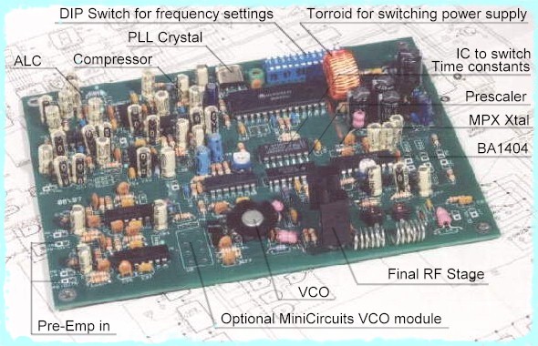
The stereo coder is a straight-forward BA 1404 stage. Interestingly enough, Wavemach decided not to use the BA1404's internal RF Oscillator and RF Buffer, using only the Multiplexing and Pilot generation circuitry.
You have a choice of two VCOs - Either a Varicap based 2N4427 transistor Hartley Oscillator stage or a MiniCircuits VCO module ( to be purchased separately)
A Class C stage based on another 2N4427 acts as the final RF power stage which is followed by a 6 component filter before going to the antenna. A standard rectifier and capacitor sampler converts a small part of the RF output into DC for use as a power indication.
The PLL is based on the MC145152P2 Synth chip while a MC12011P acts as the prescaler. The PLL can be programmed via a DIP switch from 75 MHz to 125 MHz.
One of the Op-amp stages in the NE5532AP is used as an active PLL loop filter. This is considered better than passive loop filters because active loop filters can have gain and swing their output control voltage right close up to the supply voltage ie 12 Volts. The passive loop filter can at the most output a DC signal equal to the power supply of the logic chips ie 5 Volts. If the range of the Error control voltage is higher, the designer does not need to design a very sensitive VCO ie around 1.5 MHz per Volt instead of 4 MHz per Volt. If the VCO need not be very sensitive, it is more resistant to stray signals in the Error voltage, resulting in less phase noise and spurii.
There is an interesting bit of circuitry that switches the time constants of the loop filter for a fast lock up time initially and then a longer time constant later on for good bass response. This is designed by integrating the LD signal of the Synth by yet another of the Op-amp stages and feeding that signal to a MC14066B switch. When out of lock is detected, the electronic switch shorts out one of the time constant resistors, reducing the time constant. The documentation states "All this circuitry was added to save you waiting 5 seconds for lock to occur"
The Philips NE57x family is ideally suited to make ALC and Compressor circuits. See Philips Compandor Cookbook PDF, Philips NE572 ALC PDF and the Philips Compandor Application Notes PDF. You will soon find that a good Limiter and Compressor are totally essential if you want to compete with the Pro stations on sound quality and perceived loudness.
The same PCB can be used to make various different combinations of the kit : Mono or Stereo; with/without the ALC & Compressor circuitry; with the 2N4427 based VCO or the optional MiniCircuits VCO module.
The internal Power circuitry is quite complicated. The RF stages are fed +12 Volts. The Quad Op-amps work at split +12/-12 Volts. The Prescaler is fed -5.2 Volts. The Synth chip supposedly works at 5 Volts ( or is it 8 Volts ??? a 78L08 voltage regulator is supplied).
A switching power supply circuit is built in on the same PCB. It revolves around a MC33063AP1 Chip. This generates the -12 Volt line which is also regulated by a 7905 IC to give a -5.2V line.
The components are of high quality. Dave takes the trouble of packing each type of component in its own bag, so all the resistors have their own pouch while the caps are in their own bag.
Documentation :
I was quite impressed with the amount of documentation
included : 22 pages in total that contained soldering
instructions, theory of operation, Circuit Diagram with
values :) , a page on how to identify component values,
DIP switch settings for various frequencies, test procedures to
align the various stages, suggestions on which building blocks to
use to best suit your requirements ...
Impressions :
Seems like a nice enough kit obviously designed by a hobbyist,
for other hobbyists who need the various building blocks to fool
around and experiment till they reach the sound they like. You
get most of the Audio processing stages you need on one PCB,
rather than buying separate kits. Believe you me, the moment you
start transmitting, you will realise the value of the built in
ALC and Compressor ! They are totally essential if you need a
"loud" but clean sound to compete with the pros.
The BA1404 is used in a cost-effective attempt to experiment with Stereo. Purists seem to complain at its specs. But I guess if you get this kit to experiment with its various building blocks, at the right time you can opt to get another MPX generator, disable the internal BA1404 MPX building block and just plug your new module in.
The bunch of circuitry to get faster lock times is quite unnecessary for this kind of kit. The documentation says that lock time without the quick-lock circuitry is only 5 seconds !! Adding a lot of circuitry just to reduce this lock time to 0.5 sec is futile. And any extra circuitry that is not helping you is obviously harming you. You would raise the chances of adding noise into the active loop or clicks when the switch switches in. I would have rather used the lock detect feature to power down the final RF stage when PLL is not locked ( like the new Broadcast Warehouse PLL), or failing which, atleast have a LED that lights up when the loop is locked ( like Veronica).
Actually some professional Exciters do have dual time constant circuitry. The problem is that if you are designing serious Exciters with excellent low frequency response and low phase shift, you might need a PLL loop constant in the order of 10 minutes. Some manufacturers claim a primary loop constant of around 2 hours in their professional gear. Now we all can understand that nobody will wait that long for PLL lock so you do need a circuit that locks fast initially and then changes loop constants. But in a beginners kit using a BA1404 for the stereo MPX, the dual time constant circuitry does look a bit out of place. However, in keeping with the kit's central theme, it's there in case you like experimenting with it. Maybe Mod No 1 would be to change the primary loop constant to about 5-10 minutes or more and check if that assists bass response in stereo mode. In this case, the dual time constant circuitry would come in real handy !
To me, the intricate internal power supply requirements are just unnecessary complications. As the circuit is designed to use balanced voltage supplies as well as a -5.2V needed to drive the Prescaler, a small low power switching power supply circuit is needed to generate the negative voltage lines. This needs a switching IC that basically feeds high frequency pulses into a torroid coil. The back voltage on the coil generates the negative voltage. The IC adjusts the frequency and duty cycle of the pulses so that the voltage is regulated at -12 Volts.
In a RF circuit where one is trying to reduce stray RF signals, it does not seem right to design in a switching power supply circuitry with its high frequency pulses on the same PCB.
There does not seem to be any particular advantage of having a balanced power supply and DC coupling between the Op-amp stages especially as the circuit still uses unbalanced audio input signals. To be fair, there is no disadvantage either, except that designing the Op-amp stages to use only a positive Vcc would have made a much cleaner, cheaper and reliable circuit with fewer components.
Why design the Prescaler IC to use -5.2 Volts when it or another equivalent that uses +5 volts could have been easily used ? Now you need a -5.2V regulator IC, another extra device that increases costs and could blow up sometime.
For the sake of simplicity in beginner's kits, I would have avoided a design with -12V and -5V requirements.
Kit builders will thoroughly enjoy making and using the kit. I am sure that the Wavemach will sound better than a Ramsey BA1404 kit due to the onboard active15 KHz low pass filter , ALC and Compressor, but the BA1404 will be the limiting factor on S/N and distortion. It does have more RF power output than a Ramsey FM25 (upto 2.5 W if you use the optional FMB2 RF Amp module).
The basic premise of having many Audio building blocks on the same PCB is an excellent idea, possibly marred by the choice of split power supplies, on-board switching power regulator and unnecessary dual time constant circuitry.
Wish list :
A) Simpler internal power supply requirements without a switching power supply.
B) Lock LED
C) Better Stereo Generation kit as an option to the on-board BA1404
D) Optional LCD for frequency readout
E) Spectral output graphs in the documentation and at the Wavemach Web site
F) Circuit Diagram on the Wavemach Web site
Wanna have your own page here, write
about your own experiences, own review, refute existing review,
add comments to existing review, publish your circuits ?
Contact
me
My
review of the Broadcast Warehouse 1W PLL Exciter with LCD 08 Aug 1998
My review of the Mighty MAX-1 FM
Exciter 02 May 1999
Page started on 20 Dec1998. We have had page
loads since counter reset on 15 May 2000.