| What's Inside A Mobile Phone |
SINGLE BOARD DUAL-BAND HANDSET REFERENCE DESIGN FOR GSM900 & GSM1800 (using the Mobilink MTI-1400 reference design as an example)
| User
Interface · Foreign language fonts, incl. Chinese · Flexible Phone book - Store numbers in phone (ME) - SIM Abbreviated Number Phone Book - SIM Fixed Number Dialing · Stores last 10 numbers called & received · Generate DTMF tones during call · Speaker/sidetone/mic amplification control · Visual indication of remaining battery life · Integrated data and fax adapters Software & Services · Full Rate/Enhanced Full Rate Speech with DTX · Short Message Services (SMS) · A5/1 and A5/2 encryption · Group 3 fax & Ph. 2 Supplemental services · GSM data service -Full rate 9.6, 4.8, 2.4 Kbps -Half rate 4.8, 2.4 Kbps · Hardware support for Phase 2+ data service: -14.4 Kbps data service · Layers 2/3 & MMI software supplied -Type Approved GSM Phase 2 protocol stack The MTI-1400 Reference Design is a breakthrough in design compactness, performance and quantity of features. This single-board design shows Mobilink's capability to provide the total solution for low-power GSM multi-band handset applications. By using the circuitry and software employed by the MTI-1400 design, customers can quickly and easily create a unique product to their own specifications. |
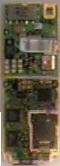
The
Mobilink MTI-1400 Reference Design above is
a dual-band GSM handset on a single PCB. This solution demonstrates how a Mobilink ML2000-family chip can be used to create dramatically smaller dual-band handsets, at lower costs than current multi-board solutions. The single-board design greatly simplifies the manufacturing processes and enhances product reliability. Voice quality can be either Full Rate or Enhanced Full Rate. Higher rate wireless e-mail and data transfers are possible via Phase 2+ 14.4 Kbps data service. The long talk and standby times of the MTI-1400 Handset Reference Design results from the use of a low, 2.8V supply voltage and intelligent power management, including power-down scheduling for on-chip functions and external components during inactive intervals. The very long standby time is achieved via smart microprocessor scheduling and power-efficient sleep-mode design. To accelerate our customer's product
development cycle, we also offer total system solutions including the evaluation board,
complete system software, and extensive hardware and software support through Full Type
Approval (FTA). |
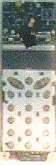
| Designed
to ensure low-cost production goals, Mobilink employs a six-layer and five-mil PCB design
rule process. The drill hole diameter is no smaller than 10mil to avoid the extra cost of
optical drilling. Blind-via technology is applied instead of expensive micro-via design.
The result is approximately 1200mm2 of baseband circuit area and 2800mm2 of RF circuit
area. All baseband and RF circuitry fits onto a single board. Since it is a single board design, manufacturing costs are reduced relative to conventional multi-board designs. Connectors exist for the LCD panel, SIM card, battery charger, antenna and system accessories and one side of the board has keypad patterns. Software components for the LCD and keypad are easily altered for specific changes and the memory system can be changed from the 128K x 8 SRAM and 512K x 16 FLASH provided. The flexible architecture of the baseband codec hardware allows customers to choose from a wide variety of microphones and speakers. |
Starting
with this compact design, Mobilink's engineering teams work with customers in BOM
optimization, and feature and form factor customization, in order to match every detail of
the requirements. Mobilink's in-house expertise allows customers to add or alter software
and mechanical features or hardware interfaces, and quickly get a product design through
Type Approval and field trials. This industry-leading design demonstrates Mobilink's
commitment to low-cost, low-power, high-performance RF design. For more information, please contact: e-mail: info@mobilinktel.com |
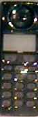
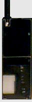
Select an area inside this demo cellphone design:
| Component | Purpose |
| Microphone | Captures your voice for conversion from analogue to digital mode |
| Speaker | Allows monitoring of remote phone |
| LCD Display | Shows Call, Phone, Signal & Network Info |
| Keypad | Allows access to specific remote phones |
| Battery + Meter | While battery housings on cellphones are standard input deigns, some cellphones also have some "battery processing" intelligence built in. For example, they will check the charge level to start or stop the charge when the phone is connected to a desktop, car or quick charger and even automatically discharge the battery for you when necessary. This is usually linked to the LCD display and to an audible beep to warn you of the battery charge status. |
| LED Lights | Status Information, usually Green, white & Red. |
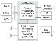
| Digital Signal Processor | The DSP chipset is a critical component. It co-ordinates the voice, SMS and data/fax features of a cellphone. It processes speech, handles voice activity detection, as well as discontinuous GSM transmission and reception. Another section amplifies the input signal received from the microphone, while another converts this microphone voice signal from "analogue" to "digital". The digital conversion is necessary because the GSM cellular standard is a completely digital system. |
| CODEC | This DSP's voice processing is done in tandem with highly sophisticated compression technique mediated by the "CODEC" (compressor/decompressor) portion of the cellphone. T |
| RF Unit | The CODEC chipset instantly transfers this
"compressed" information to the cellphone’s Radio Frequency (RF) unit. This
RF unit, which is essentially the transmit and receive section of the cellphone, then
sends out the voice or data information via the cellphone antenna, over the air and on to
the nearest cellular base station - and ultimately to your call destination. The incoming voice also travels much the same route, although it is first uncompressed from it’s incoming digital form into an audible analogue form which is then piped out as sound through the cellphone’s speaker. This analogue-to-digital and digital-to-analogue voice conversion via the CODEC is done at very high speeds, so that you never really experience any delay between talking and the other person hearing you (and visa versa). |
| SIM Card Reader | When you switch on your phone with a "live" SIM card inside, the subscriber information on the chip inside the SIM card is read by the SIM card reader and then transmitted digitally to the network via the RF unit. The same route is followed when you hit the Call button (and it’s variants) on the cellphone: the number you’ve inputted is instantly and digitally transferred to the network for processing. |
| External Connectors | At the bottom of most cellphones there is an external connector system. You can usually plug in a data/fax adapter, or a battery charger, or a personal hands free device, or a car-kit with external antenna connections. You’ll also find many with separate "speaker" and LED lights that are activated when the phone rings and/or when the battery is low. Many phones also have tiny LED lights under the keypad that light up when you press a key and/or when the phone rings. |
| On-Board Memory | Many cellphones also have a certain amount of on-board memory chip capacity available for storing outgoing telephone numbers, your own telephone number, as well as incoming and outgoing SMS messages. Some allow copying between the (limited) memory on the SIM card and the phone’s own internal memory. |
| Antenna System | Cellphone manufacturers are implementing many weird and wonderful permutations of antenna system designs. While some are stubby, fixed types, the most predominant designs though are those with thin, pull-out steel rods all of whom usually fit snugly into a special antenna shaft. These antenna designs, be they the stubby or pull-out types, all conform to the same circa 900 MHz frequency transmit and receive range required by the GSM specification. |
Disclaimer!!
The above is a merely a very rough, schematic
interpretation of what is inside a GSM cellphone.
The components will vary from cellphone model/brand/design to cellphone
model/brand/design.
We will not be held liable for use or misuse of this data.